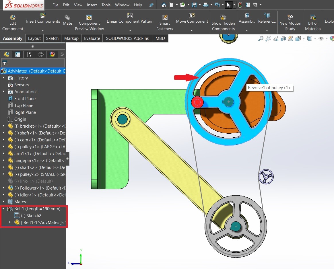
Belt/Chain Assembly Feature simulates a belt, chain, pulley or sprocket. It has the ability to include more than two components. This feature adds appropriate mates and relations to give you that desired rotational results. It will also create a sketch containing arcs and lines describing the path of the belt.
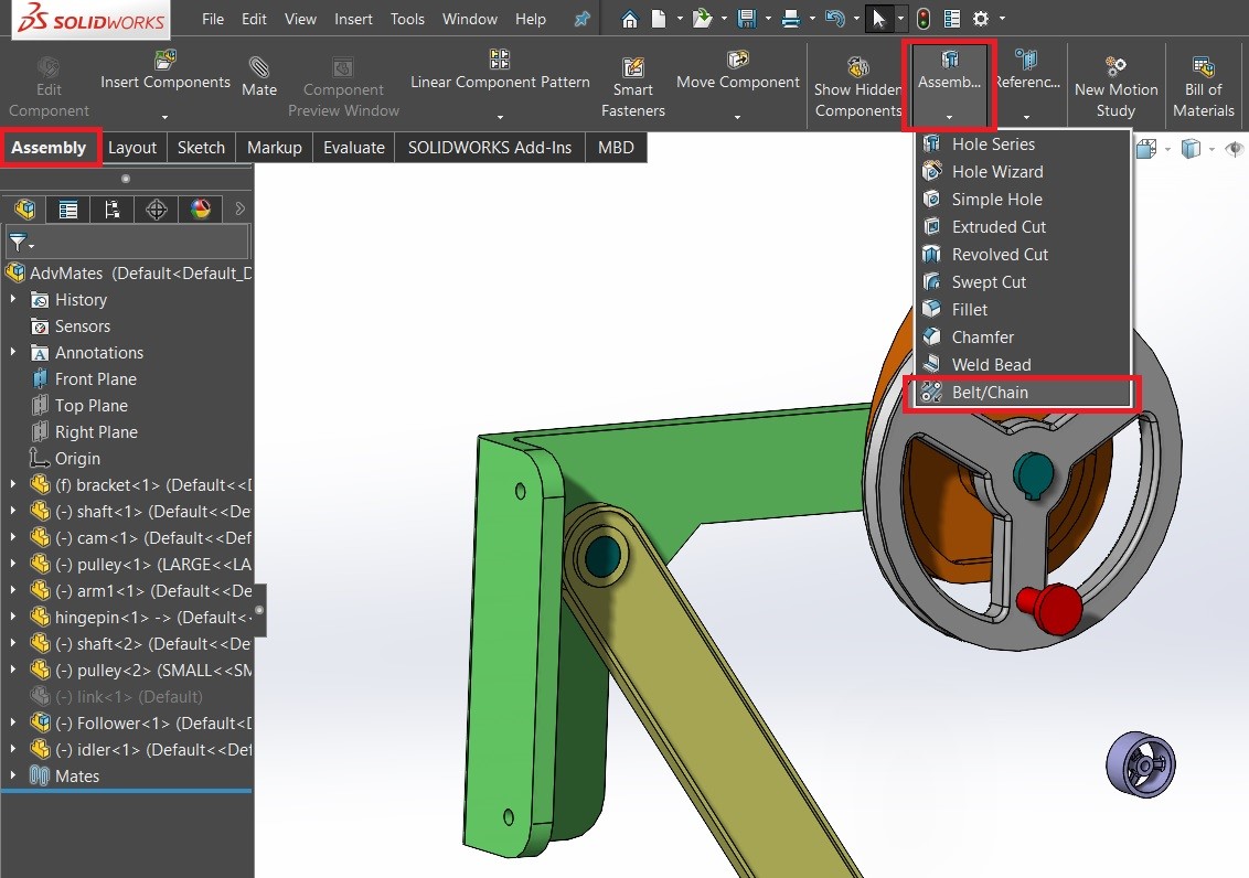
To find the Belt/Chain Assembly tool, Click Assembly tab, expand Assembly Feature icon and select Belt/Chain.
Clicking the Belt/Chain mate will show multiple options on of which category is:
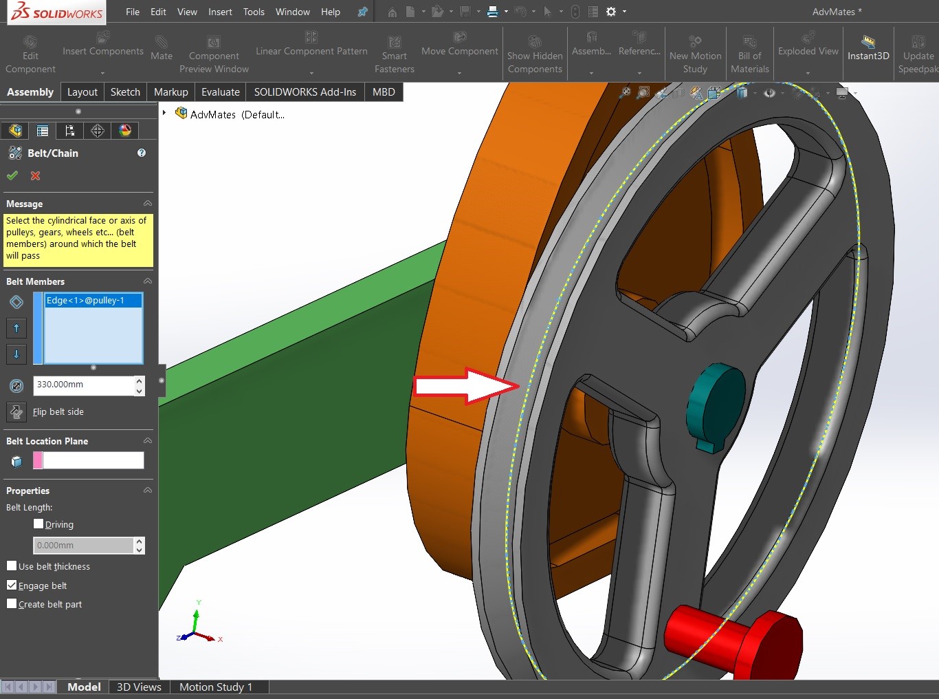
Belt Members: In this section you can select edges of different pulleys/sprockets which you have to mate. Multiple bodies can be selected. As seen in the picture above, we have selected a groove edge of the first pulley and it is correspondingly showed in the feature property manager. It also shows the diameter of the pulley.
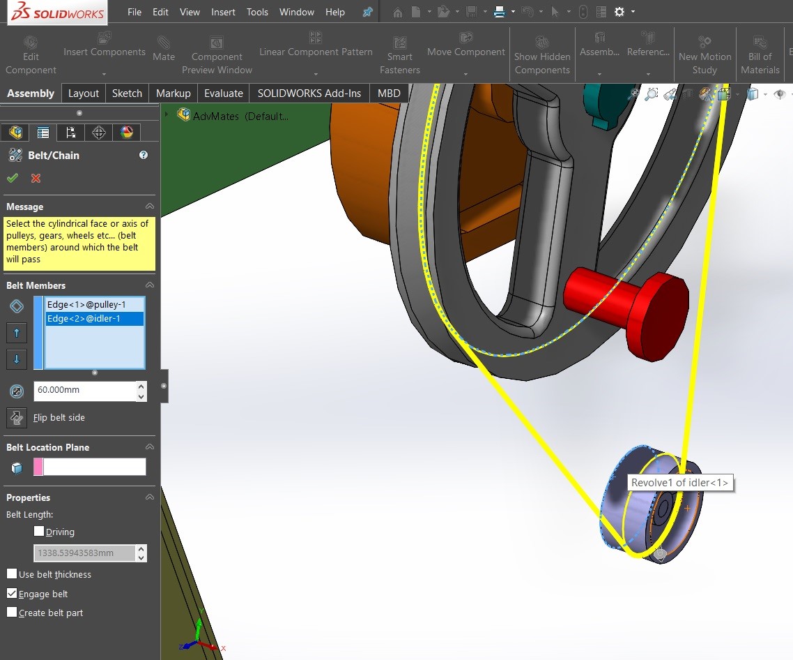
Go on selecting one by one all pulleys’ edges to form a belt, it shows up the preview of the belt.
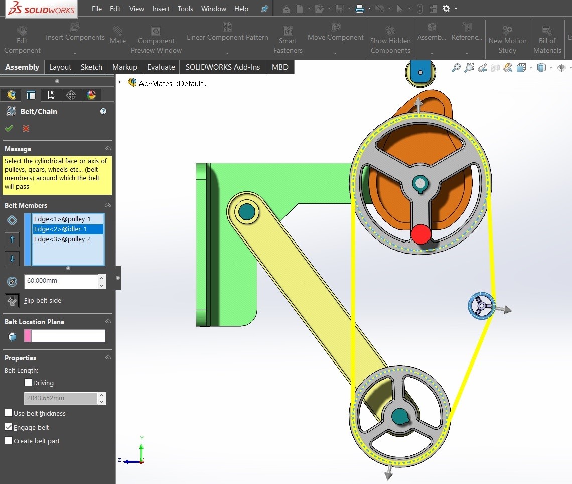
Selecting all the parts shows a preview, with the direction arrows. You can always flip the direction of belt with respect to the pulley, As shown in the below picture done for the Idler pulley.
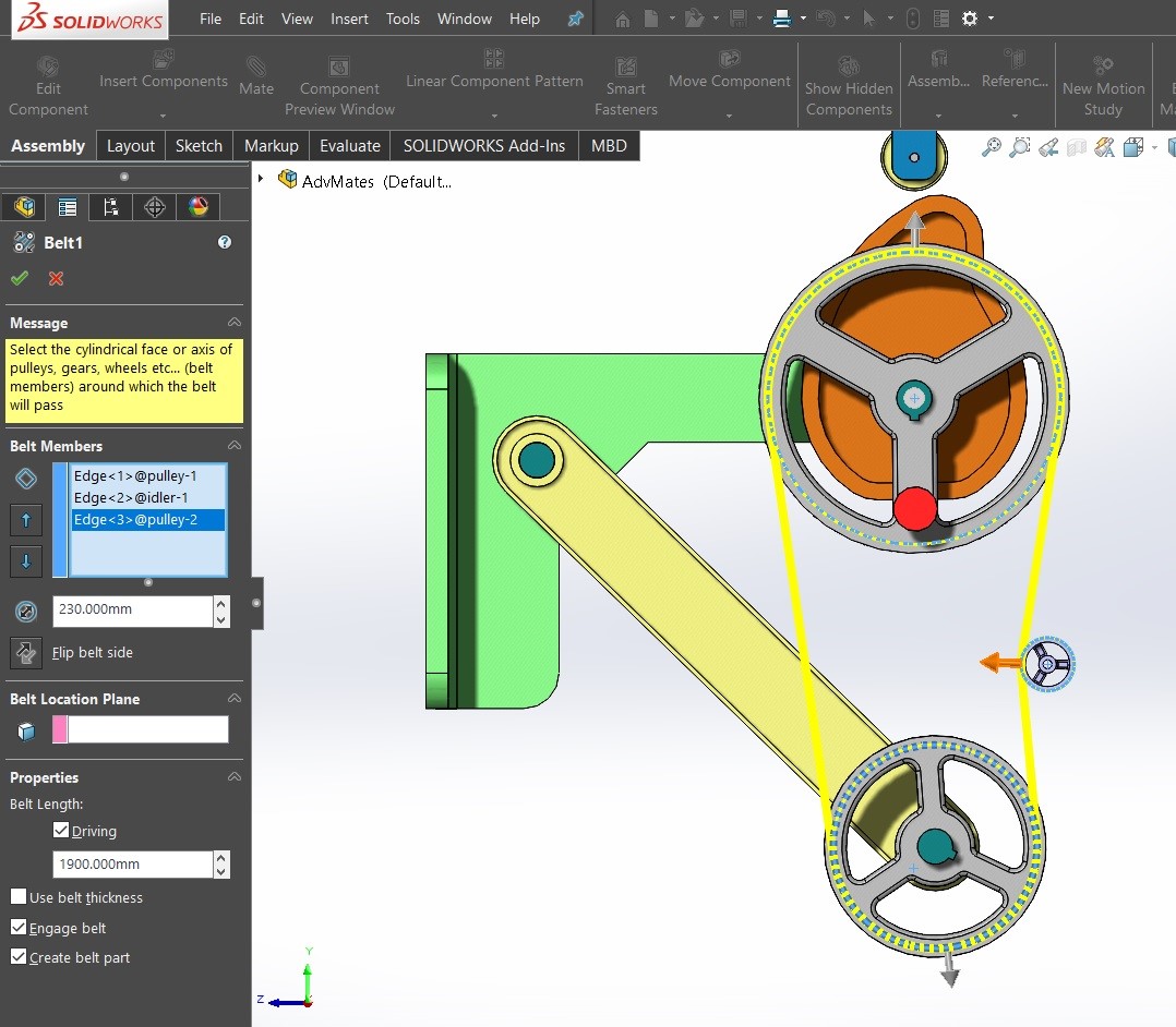
In the Properties section, you can give target length to the belt, which makes a pulley change its position as per the length of the belt (you can notice the bottom pulley changed its position as we gave a target Belt length.
Furthermore there are options to create a separate part for the belt and to give thickness to the belt. After all this, click Ok and rotate any of the face of a pulley, you can see other pulleys rotating as per the belt, as shown in Below Picture.